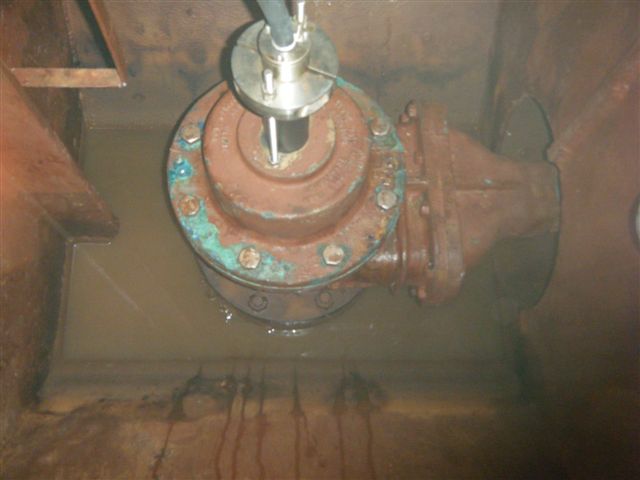
This ship was dry docking in one of the shipyard locally.
The vessel has not replaced the transducers for the pass 10years. Consider the transducer very reliable. They come with 50Khz forward transducer and 200Khz aft transducer. Normally 200Khz transducer is used to detect shallow water depth as compare to 50Khz transducer. Basically, the LAZ5000 display was faulty due to unable to switch on. Replaced with LAZ5100 Display unit. The crew also complaint the slave display DAZ25 not showing correct depth when the Master display was working well with good depth before.
I have used my laptop to simulate a $DBT or $DPT at old DAZ25 found unable to update. So replaced with new DAZ25 and found working well with simulated nmea from laptop.
The first time went down to inner tank to locate the forward 50Khz transducer was a good experience. Caution need to be observe, ventilation must be provided with blower working in good condition. Working in confine space would require a gas detector been carried around the waist in case of oxygen level fall below 19percent or above 21percent, it will beep to warn of danger in confine space. Excess of CO2(Carbon Dioxide) can also be dangerous in confine space. So minimum of 2 person entering tank was necessary to prevent accident and seek help in case of accident do happen.
It was fully dark with a funny smell. Torch light should be strong and bright to find the right place. We enter into the inner tank from main deck with at least 4 levels down the vertical ladder before we reaching the bottom. The location was very small and only allow one person to reach the transducer. Finally we found 3 x transducers and the most left was identified as 50Khz echo sounder transducer and the smallest among compare to speed log transducer to the right.
I have instruct yard workers to remove the transducer from outside the bottom since ship was at dry dock. Cut the wire from inside around 1meter from transducer so that remove from outside would be easy. After removing the 3 bolts from outside transducer, we manage to slowly twist the transducer from side to side to rotate the transducer and finally made its way out. Replaced with new transducer is also tricky as the old transducer cable is useful to guide the new transducer cable to run through the trunking and all the way up to the junction box in a deck below main deck.
Finally the new transducer was fixed and connected. Display showed good reading after ship undock at the shipyard. Please see some of the pictures taken.
Monday, May 3, 2010
Wednesday, April 21, 2010
KW950E interface negative 35V step Gyro heading to 38400bps $HEHDT
This is a procedure to interface 4 wire negative step at ref. 35V to 38400bps nmea output. I had tested working on a tanker recently with MK37 Gyro compass.
I had study this connection and document down the procedure.
1. Connect step input to SK2, R+ = Ref, S1 = S1-, S2 = S2-, S3 = S3-
2. Link S1+, S2+, S3+ and R+ together
2. Set SW1 to 0000 1010 for 38400bps $HEHDT
3. Connect nmea output to SK3 data output A and B
I had study this connection and document down the procedure.
1. Connect step input to SK2, R+ = Ref, S1 = S1-, S2 = S2-, S3 = S3-
2. Link S1+, S2+, S3+ and R+ together
2. Set SW1 to 0000 1010 for 38400bps $HEHDT
3. Connect nmea output to SK3 data output A and B
Tuesday, April 20, 2010
KW950E interface serial Gyro heading from low speed 4800bps to 38400bps
As this has become a requirement to connect high speed nmea Gyro compass signal to radar. Typical set at baudrate of 38400bps.
KW950E was able to fulfill this requirement. During the interface of C-plath nmea Gyro signal to Sperry marine VMFT radar, we used KW950E to connect input with 4800bps and ouput 38400bps to both radar and both ECDIS.Be very careful, only one setting works with KW950E from NMEA 4800bps to 38400bps. Below were the procedures :
1. Connect 24Vdc into SK1 of KW950E
2. Connect 4800bps $HEHDT into SK5 data input no.2 - A and B
3. Connect data output into SK3 output no.1 - A and B
4. Set SW1 to 0001 1110 for 4800 input, 38400 output and HEHDT
5. Switch on power and you will get to see display blinking, press either increase or decrease to acknowledge the presence of signal input.
Setup completed. Please see attached pictures to see the connection details.
Wednesday, April 14, 2010
Ship at OPL
I was attending a sperry marine BME radar service onboard a container at eastern OPL. Travel in the morning and return at night. Some of the very beautiful ships i have taken along the way to service trip.
Sunday, April 4, 2010
My first radar experience in 1990 - Decca TM 1626
I still remember the first radar i had encounter fall all the way back in 1990. It was ARPA Decca 1626 True Motion X-band radar. During that time, i have no idea what is this piece of equipment doing good for us? I see yellow patches on the PPI(Plan Position Indicator) screen rotate in clockwise circular motion. This yellow patches were known as video or targets or return echo from the transmission of radar which help us identified the objects around us up to 48nm. Although the radar screen can show up to 96nm, in practice, it was not possible to achieve 96nm due to the power output from a 25Kw magnetron. It was a good piece of equipment at that point of time. This equipment had more than 20 slot cards in the lower rack which help in the processing of radar video, calculate dead reckoning function...etc. I cannot remember whether it was connected with GPS as at that time only transit satelite was available. I do remember this piece of equipment can acquire a maximum of 20 targets at any one time. It was one of the latest technology at that time.
Kelvin hughes radtrack radar was also one of the ARPA radar with latest technology at that time.
Then in 1991, there comes a PC radar which can acquire 50 targets at one time. This piece of equipment process radar video in a digitize format. The screen changes from PPI to a multicolor VGA monitor.
It was the DB2000I display processing monitor interface with Decca I-band transceiver. DB2000I comes with a floppy drive slot, powered by a few processors cards which run by intel microprocessor 80286 and 80287.
These processors include RDD, RTS and OPC processor. Raw video was converted by radar scan converter from analog to digital. The instructor from Norcontrol Norway - Mr. Paul Herfjord had travel down to Singapore in Jan 1992 for the DataBridge2000 technical training course.
Since then i have been servicing these few pieces of equipments from these few companies until now.
Tuesday, March 30, 2010
Sperry Marine electronic C-plath Mode X Mk1 Gryo compass annual service
The ship's captain complaint of gyro compass keep rotate in clockwise direction. Attend onboard and found as discribed by ship crew. Enter setup access code 610, checked gyrosphere current approx. 265mA and temperature approx. 72deg - very high.
Switch off the gyro compass and waited one hour for gyro sphere to settle. Remove the upper housing and found gyro liquid had evaporated quite a lot so causing the sphere overheat. Another reason for lost of gyro liquid is due to top cover cracked line whereby gyro liquid evaporate through the escaped crack line. After replaced new gyro liquid and enter access code 757 for annual service done, apply epoxy to the crack line and surrounding of the ventilation valve. Wait till epoxy dry, reinstall the gyro sphere back into housing
Started the gyro and observed the gyro sphere current approx. 267mA normal and temperature approx. 50deg, on the high side but still acceptable. Found that closing the front cover will cause the temperature to increase rapidly till 70deg.
Checked and found the fan behind the gyro housing was weak but working. Advice crew to install additional fan to cool the temperature of gyro.
After one month now, no complaint from ship crew so far, so i guess the problem had solved.
Please see attached pictures.
Sunday, March 28, 2010
MX Marine / Simrad MX420 DGPS System
This is a container ship where the crew complaint that the Sperry Marine VMFT ECDIS and Radar have constantly show RAIM unsafe alarm from both DGPS no.1 and 2(MX420 with MX521 Antenna).
Go to MX Marine website and realise the following :
We have recently found that due to week rollover limitation, the date from MX421 D/GPS antenna is reset to Aug. 1, 1993. This happens when power is recycled in the unit. All other navigation information is not affected.
This week roll over issue has been fixed in the new software v4.902.
So follow the instruction carefully from MX521_6705.zip file to connect as follow. Download the 521-521v6705.bin into MX521A antenna via program rightarm.exe, select erase and program. After approx. 30mins of reprogramming. It shows successful on my laptop. So power down the MX521A antenna. Waited for 5mins, try to power up and reconnect all wire with Display unit MX420, found no communication between Display and Antenna. Connect back the same wire with laptop com1 setting. Found unable to reboot MX521A Antenna. This was strange as the equipment should recover by itself. For this case it was dead.
So finally, need to replace a new MX521A antenna with software version 6.8 and it works fine. Crew need to monitor the situation to see if the problem has fixed with the new software installed.
Please see attached pictures.
Enjoy!!
Subscribe to:
Posts (Atom)