祝大家新年快乐
Friday, December 31, 2010
Sperry Marine VMFT Radar
I have to say that so far i have come across quite a number of radars in the market including furuno and JRC radars make from Japan, Kelvin Hughes radar from UK, Kongsberg Maritime radar DB10 from Norway. Furuno radar has quite a big share market in commercial marine due to it's cheap and good nature. I have to say my preference is still sperry marine radar. It was a perfect match when they combine the Decca radar transceiver with the latest technology of display unit - Vision Master FT. This has make it so good and easy to commission and service. The operation aspect is also great as it can combine ECDIS and radar in one console. So ship owner who wanted to fulfill the IMO requirement and wanted to upgrade their radar display with old BridgeMaster E either X or S band transceiver has become much more easy. The time taken to commission a VMFT radar display has shorten very much, so shipowner can upgrade the radar without been delayed for the chartered time and $$ lost due to delay in cargo delivery. Today is New Year Eve of year 2011, I wish all people i know, including my peers, friends, relatives and family member have a good start and great year in 2011. I hope and wish all of them good health, great jobs and all wishes come true.
Wednesday, July 21, 2010
C-Plath Gyro Bearing Repeater
This is a tanker. Ship request to replace both port and stbd wing bearing repeaters. Consider very reliable since it has been working for the pass ten years. Checked the bearing repeater by pressing on the sync button. Bearing repeater will spin anti-clockwise for approx. half turn and sync button will blink. Pressing the sync button again and the bearing repeater will align itself to the correct heading and sync button will stop blinking.
Remember to tape pin 1 and 2 which is the 24Vdc supply. Disconnect the 12 pins from the old bearing repeater and reconnect the new 12 pins. Remember to connect from pin 12, 11, 10....until 1, 2. As try to connect 24Vdc supply last as it will start up the bearing. You will get to see a little spark when connect pin 1 and 2 if you did not switch off the breaker. This is a short cut method if you are running out of time, but was not recommended as it will sometime cause shorting to the equipment. Also remember to connect pin 7 to pin 2.(I.E. Short circuit CP/NMEA to 0V)
After replacement, found the dimmer pot for both port / stbd bearing repeater had jammed and cannot be turned
in either direction. So need to replaced connection box in order to make it work properly. It was a 10Kohm potmeter where LED light on the surrounding of bearing repeater was situated to light up the repeater at night for easy visibility.
Remember to tape pin 1 and 2 which is the 24Vdc supply. Disconnect the 12 pins from the old bearing repeater and reconnect the new 12 pins. Remember to connect from pin 12, 11, 10....until 1, 2. As try to connect 24Vdc supply last as it will start up the bearing. You will get to see a little spark when connect pin 1 and 2 if you did not switch off the breaker. This is a short cut method if you are running out of time, but was not recommended as it will sometime cause shorting to the equipment. Also remember to connect pin 7 to pin 2.(I.E. Short circuit CP/NMEA to 0V)
After replacement, found the dimmer pot for both port / stbd bearing repeater had jammed and cannot be turned
in either direction. So need to replaced connection box in order to make it work properly. It was a 10Kohm potmeter where LED light on the surrounding of bearing repeater was situated to light up the repeater at night for easy visibility.
Wednesday, June 23, 2010
C-plath Gyro Mk10 Mode 1 annual service
This is a bulk carrier. It was due for annual servicing while ship approx. one year old. New build from China yard. The housing was black in color. No mercury needed for this model of gyrosphere stock no. 074829. Checked the gyrosphere current before switching off for servicing = 237mA, temperature = 46deg. Ph. Bridge = 1 mV. Locate 24Vdc and 230Vac ship supply breaker. Switch off both power supply to cut the power. Allow gyrosphere to spin down for approx. 1 hr. Remove the container by unplug the supply and pickoff connector and lower the housing by lifting and twisting the unit to the right slightly. As usual, allow the old gyro liquid to flow out from the lower nu with red O-ring. Remove the hex screw from upper housing. clean the sphere. Replaced O-ring. Found that gyrosphere current can also be observe from R103. By putting multimeter lead across R103 at master board and measured in AC Volt. The value show in Volt or mV is equivalent to Current in mA. Be careful if you observe gyrosphere keep rotating in anti-clockwise direction, make sure the ribbon cable located on the outside of housing was intact. Also open the housing to make sure no foreign object found inside the sphere. Especially not to use tissue paper to clean the sphere as tissue paper can tear and stick onto the sphere and cause problem after overhaul.
Wednesday, May 26, 2010
Monday, May 3, 2010
LAZ5100 Echo Sounder Transducer replacement
This ship was dry docking in one of the shipyard locally.
The vessel has not replaced the transducers for the pass 10years. Consider the transducer very reliable. They come with 50Khz forward transducer and 200Khz aft transducer. Normally 200Khz transducer is used to detect shallow water depth as compare to 50Khz transducer. Basically, the LAZ5000 display was faulty due to unable to switch on. Replaced with LAZ5100 Display unit. The crew also complaint the slave display DAZ25 not showing correct depth when the Master display was working well with good depth before.
I have used my laptop to simulate a $DBT or $DPT at old DAZ25 found unable to update. So replaced with new DAZ25 and found working well with simulated nmea from laptop.
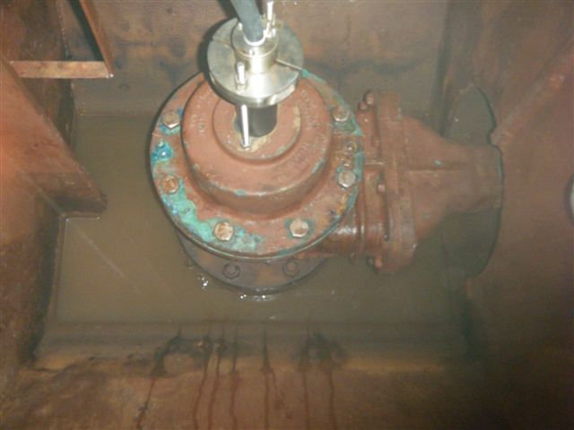
The first time went down to inner tank to locate the forward 50Khz transducer was a good experience. Caution need to be observe, ventilation must be provided with blower working in good condition. Working in confine space would require a gas detector been carried around the waist in case of oxygen level fall below 19percent or above 21percent, it will beep to warn of danger in confine space. Excess of CO2(Carbon Dioxide) can also be dangerous in confine space. So minimum of 2 person entering tank was necessary to prevent accident and seek help in case of accident do happen.
It was fully dark with a funny smell. Torch light should be strong and bright to find the right place. We enter into the inner tank from main deck with at least 4 levels down the vertical ladder before we reaching the bottom. The location was very small and only allow one person to reach the transducer. Finally we found 3 x transducers and the most left was identified as 50Khz echo sounder transducer and the smallest among compare to speed log transducer to the right.
I have instruct yard workers to remove the transducer from outside the bottom since ship was at dry dock. Cut the wire from inside around 1meter from transducer so that remove from outside would be easy. After removing the 3 bolts from outside transducer, we manage to slowly twist the transducer from side to side to rotate the transducer and finally made its way out. Replaced with new transducer is also tricky as the old transducer cable is useful to guide the new transducer cable to run through the trunking and all the way up to the junction box in a deck below main deck.
Finally the new transducer was fixed and connected. Display showed good reading after ship undock at the shipyard. Please see some of the pictures taken.
The vessel has not replaced the transducers for the pass 10years. Consider the transducer very reliable. They come with 50Khz forward transducer and 200Khz aft transducer. Normally 200Khz transducer is used to detect shallow water depth as compare to 50Khz transducer. Basically, the LAZ5000 display was faulty due to unable to switch on. Replaced with LAZ5100 Display unit. The crew also complaint the slave display DAZ25 not showing correct depth when the Master display was working well with good depth before.
I have used my laptop to simulate a $DBT or $DPT at old DAZ25 found unable to update. So replaced with new DAZ25 and found working well with simulated nmea from laptop.
The first time went down to inner tank to locate the forward 50Khz transducer was a good experience. Caution need to be observe, ventilation must be provided with blower working in good condition. Working in confine space would require a gas detector been carried around the waist in case of oxygen level fall below 19percent or above 21percent, it will beep to warn of danger in confine space. Excess of CO2(Carbon Dioxide) can also be dangerous in confine space. So minimum of 2 person entering tank was necessary to prevent accident and seek help in case of accident do happen.
It was fully dark with a funny smell. Torch light should be strong and bright to find the right place. We enter into the inner tank from main deck with at least 4 levels down the vertical ladder before we reaching the bottom. The location was very small and only allow one person to reach the transducer. Finally we found 3 x transducers and the most left was identified as 50Khz echo sounder transducer and the smallest among compare to speed log transducer to the right.
I have instruct yard workers to remove the transducer from outside the bottom since ship was at dry dock. Cut the wire from inside around 1meter from transducer so that remove from outside would be easy. After removing the 3 bolts from outside transducer, we manage to slowly twist the transducer from side to side to rotate the transducer and finally made its way out. Replaced with new transducer is also tricky as the old transducer cable is useful to guide the new transducer cable to run through the trunking and all the way up to the junction box in a deck below main deck.
Finally the new transducer was fixed and connected. Display showed good reading after ship undock at the shipyard. Please see some of the pictures taken.
Wednesday, April 21, 2010
KW950E interface negative 35V step Gyro heading to 38400bps $HEHDT
This is a procedure to interface 4 wire negative step at ref. 35V to 38400bps nmea output. I had tested working on a tanker recently with MK37 Gyro compass.
I had study this connection and document down the procedure.
1. Connect step input to SK2, R+ = Ref, S1 = S1-, S2 = S2-, S3 = S3-
2. Link S1+, S2+, S3+ and R+ together
2. Set SW1 to 0000 1010 for 38400bps $HEHDT
3. Connect nmea output to SK3 data output A and B
I had study this connection and document down the procedure.
1. Connect step input to SK2, R+ = Ref, S1 = S1-, S2 = S2-, S3 = S3-
2. Link S1+, S2+, S3+ and R+ together
2. Set SW1 to 0000 1010 for 38400bps $HEHDT
3. Connect nmea output to SK3 data output A and B
Subscribe to:
Posts (Atom)